Maintenance Switch Box
 MAINTENANCE / SWITCH BOX
Maintenance Switch Box
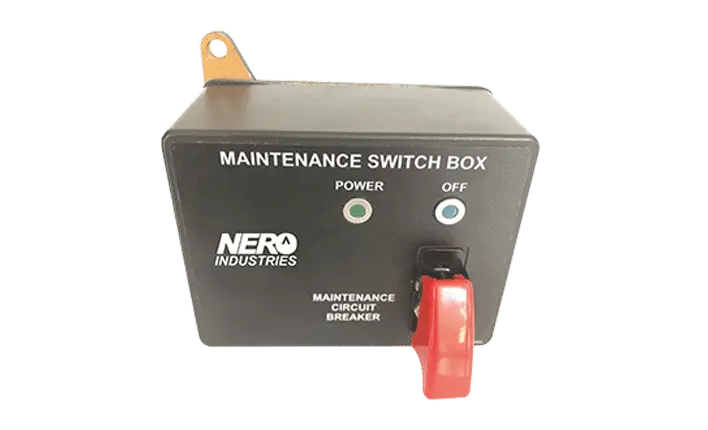
Vehicle fire suppression and safety architectures require a controlled method of disconnecting electrical power before service work begins. The Maintenance Switch Box provides a dedicated isolation point for shutting down the connected power supply during maintenance, component replacement, battery boosting or welding procedures. This controlled separation helps keep servicing activities electrically isolated from connected fire suppression equipment.
Dedicated electrical isolation and status indication for maintenance procedures within vehicle fire suppression and safety systems.
Dedicated Power Isolation for Vehicle Maintenance
The Maintenance Switch Box provides a defined point for disconnecting electrical power when maintenance work requires the connected system to be isolated. Its maintenance toggle switch allows the supply to be completely shut down before work is carried out on vehicle systems or related components.
The unit is intended for installations where fire detection, fire extinguishing or other safety-related electrical equipment must remain under controlled power management during servicing.
Electrical Separation During Service Procedures
The maintenance switch function can be used when system servicing, component replacement, battery boosting or welding is performed within the vehicle. Disconnecting the supply at a dedicated control point reduces the possibility of unintended electrical activation while work is in progress.
Integrated indicator and warning signals provide status visibility, allowing the operator or technician to identify the electrical condition of the unit during use.
Isolation16–32
VDC
Compact Control for Vehicle Electrical Architectures
The unit operates across the specified 16–32 VDC range and draws 15 mA @ 24 VDC. Its compact role within the vehicle electrical architecture allows maintenance isolation to be added without changing the fundamental purpose of the connected fire suppression or safety system.
The supplied technical data also lists IP67 protection, an operating range of -40°C to +71°C and 800 hours of salt fog resistance.
Maintenance Switch Box Highlights
Controlled Power Shutdown
The maintenance toggle switch provides a dedicated means of disconnecting the connected electrical supply.
Service Procedure Support
Power isolation can be applied during servicing, component replacement, battery boosting and welding activities.
Integrated Status Signals
The technical data identifies integrated indicator and warning signals for system-status visibility.
16–32 VDC Operation
The specified operating voltage range supports integration with the listed vehicle electrical environment.
IP67 Protection
The supplied specification lists IP67 protection against water and dust ingress.
800-Hour Salt Fog Resistance
The technical table specifies salt fog resistance of 800 hours.
Core Functions Within the Maintenance Interface
Maintenance Isolation
- Control
- Dedicated maintenance toggle switch.
- Purpose
- Disconnects the power supply when servicing requires electrical isolation.
- Procedures
- Supports maintenance, component replacement, battery boosting and welding activities.
Status Visibility
- Indication
- Indicator and warning signals are listed as integrated.
- Power Draw
- 15 mA @ 24 VDC.
- Voltage Range
- 16–32 VDC.
Environmental Protection
- Ingress
- IP67 water and dust protection.
- Temperature
- -40°C to +71°C operating range.
- Salt Fog
- 800 hours as listed in the technical data.
Application Areas
Military and Conformity References
The supplied technical information lists military environmental, electromagnetic and vehicle electrical references together with additional conformity references. The identifiers below are retained as provided.
Frequently Asked Questions
01What voltage range is specified for the Maintenance Switch Box?
The supplied technical data specifies an operating voltage range of 16–32 VDC.
02What are the operating and storage temperature limits?
The operating temperature is listed as -40°C to +71°C, while the storage temperature is -55°C to +120°C.
03How much current does the unit consume at 24 VDC?
The technical table lists power consumption as 15 mA @ 24 VDC.
04What weight is specified for the Maintenance Switch Box?
The supplied specification lists a weight of 620 g ±50 g.
05Which military electrical and environmental references are listed?
The technical data lists MIL-STD-810H, MIL-STD-461G and MIL-STD-1275E, together with UL, CE and GOST-R references.
Technical Data
Need More Information About the Maintenance Switch Box?
Contact our team for vehicle integration requirements, electrical specifications and maintenance-isolation applications.