
Emergency Switch
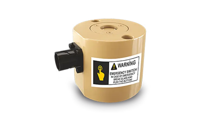 EMERGENCY SWITCH / MANUAL ACTIVATION
Emergency Switch
When a vehicle fire requires intervention from outside the platform, the suppression system must remain accessible without depending solely on the central controller. The Emergency Switch provides a dedicated manual activation path for vehicle fire extinguishing systems and is connected directly to the vehicle battery. Its independent electrical architecture allows the operator to initiate suppression during critical situations even when the main control unit is not the activation path.
Externally accessible manual activation interface with direct battery connection and electrical independence from the main fire suppression controller.
Dedicated Manual Suppression Access from Outside the Vehicle
The Emergency Switch provides a direct manual command point for activating fire extinguishers assigned to protected vehicle zones. These zones can include the crew compartment, engine bay, tyre area, vehicle body and other compartments defined by the suppression-system architecture.
Because the switch is intended for external access, it provides an additional activation route when the operator is outside the vehicle or when immediate manual intervention is required.
Direct Battery Connection Separate from the Main Controller
The Emergency Switch is connected directly to the vehicle battery and operates electrically isolated from the main fire suppression control unit. This arrangement creates a redundant activation path rather than routing the emergency command through the central controller.
The independent architecture is intended to preserve manual access to the suppression function during critical conditions in which reliance on a single control path would be undesirable.
OverrideUp to 3
Tubes
Simultaneous Manual Triggering Across Multiple Suppression Lines
The Emergency Switch can trigger up to three fire suppression tubes simultaneously, providing a manual override capability for rapid discharge across connected protection zones.
An integrated warning indicator supports operator awareness around the activation event by providing a visible or electronic warning indication.
Emergency Switch Highlights
External Manual Activation
Provides an accessible manual command point for initiating the vehicle fire suppression system from outside the platform.
Independent Electrical Path
Operates separately from the main suppression control unit through a direct vehicle-battery connection.
Three-Tube Triggering
Supports simultaneous activation of up to three connected fire suppression tubes.
Integrated Warning Indication
Provides warning indication to support operator awareness before or during emergency activation.
IP67 Protection
The enclosure is specified with IP67 protection against dust and water ingress for exterior vehicle use.
Wide DC Input Range
Designed for vehicle electrical architectures operating across a specified 16–32 VDC range.
Activation, Redundancy and Vehicle Integration
Manual Command Interface
- Access
- External vehicle installation.
- Command
- Immediate manual suppression activation.
- Coverage
- Crew, engine, tyre, body and other system-defined protection zones.
Redundant Power Path
- Supply
- Direct connection to the vehicle battery.
- Isolation
- Electrically independent from the main control unit.
- Purpose
- Provides an additional suppression activation route during emergency conditions.
Exterior Vehicle Operation
- Voltage
- 16–32 VDC.
- Temperature
- -40°C to +71°C.
- Protection
- IP67 enclosure protection with stated salt-fog resistance.
Application Areas
Certification and Test Standards
The supplied product information associates the Emergency Switch with environmental, electromagnetic compatibility and military vehicle electrical-system references, together with the listed UL, CE and GOST-R certifications.
Frequently Asked Questions
01What electrical input range is specified for the Emergency Switch?
The specified operating voltage range is 16–32 VDC.
02What temperature range is defined for operation?
The Emergency Switch is specified for operation from -40°C to +71°C.
03What ingress-protection rating is listed for the enclosure?
The supplied product information specifies an IP67 protection rating against dust and water ingress.
04What reliability value is stated for the unit?
The stated mean time between failures is 150,000 hours MTBF.
05Which military standards are referenced for the Emergency Switch?
The supplied information lists MIL-STD-810H, MIL-STD-461G and MIL-STD-1275E, together with UL, CE and GOST-R references.
Technical Data
Need More Information About the Emergency Switch?
Contact our team for manual activation architecture, vehicle integration and fire suppression system requirements.